WIRING UP
Wire Placement
You may have noticed that there is no Wire icon. This is because Proteus is intelligent enough to detect automatically when you want to place a wire. This avoids the tedium of having to select a wire-placement mode.
A connection point can connect to precisely one wire. For components and terminals there is a connection point at the end of each pin. A dot has four connection points at its centre so that four wires can be joined at a junction dot.
Since it is common to wish to connect to existing wires, Proteus also treats wires as continuous connection points. Furthermore, as such a junction invariably means that 3 wires are meeting at a point it also places a dot for you. This completely avoids ambiguities that could otherwise arise from missing dots.
To connect a wire between two objects:
- Move the mouse over the first object. The mouse cursor will change to be a green pencil to indicate that you start wire placement at this point.

- Click left to start placement and then move the mouse towards the second connection point. The mouse cursor will change to an uncoloured pencil during placement.

- During more complex routes (which involve directional changes) left click the mouse to place an 'anchor'. This commits the previous section of wire and continues to follow the mouse movement from the anchor point. Successive anchor points can be undone by pressing the BACKSPACE key.

- When the mouse is over the termination point of the wire the cursor will again change to be green in colour. Left click to commit placement of the wire.

See Also
Connectivity by Touch
It is often convenient to place a component against a wire or the pin of another component/terminal in order to make a connection. Proteus supports this method of connection as shown in the following examples.
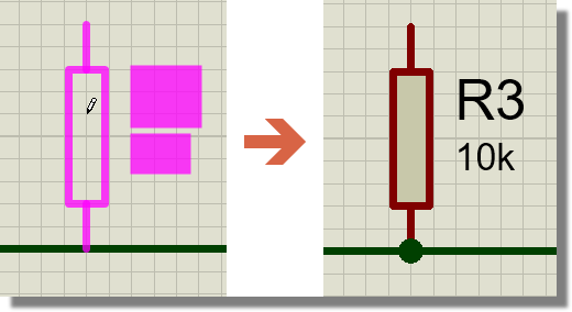
Place component against wire
If you place a component pin end directly against a wire it will be considered connected to the wire and a junction dot will be created. The component can then be moved and a wire will automatically be placed.
Place component against terminal or component pin
If you place a component such that a pin end on the component is directly against another component pin end or a terminal end on the schematic it will be connected to that component or terminal.

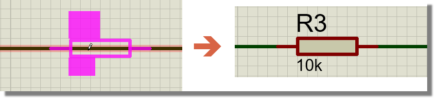
Place (2-pin passive) component in the middle of a wire
If you place a passive component (e.g. res, cap) in the middle of a wire it will insert into the wire connection and both pins of the component will be connected.
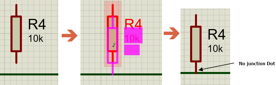
Place component and then drag onto wire
If you place a component on the schematic and then separately drag it onto a wire it will not connect. No junction dot is created. The part must be placed directly on to the wire in order to make a connection.
Dragging a component on to a Junction dot
You can connect a component to a junction dot by placing it or dragging the pin end on to a junction dot.
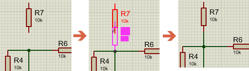
Place component and then drag onto component / terminal pin
If you place a component onto the schematic and then separately drag the component such that a pin touches the end of a component pin or a terminal pin it will form a connection.
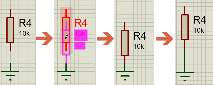
Copy and Paste component pin end onto wire
If you copy and paste a component and position the paste onto a wire, it will not connect. The same rule applies as when dragging an already placed component on to a wire.
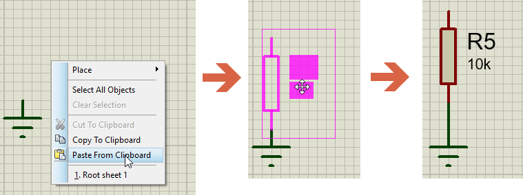
Copy and Paste component onto another component pin end or terminal end
If you paste a component or a terminal on to another pin end or terminal it will create a connection.
The following basic rules of thumb may be helpful:
- If you are placing the component you can attach to another component, wire or terminal directly.
- If you are dragging the component you can attach to another component pin, junction dot or terminal.
- If you are copy and pasting you can only attach it to a pin end, a bus pin, a junction dot or a terminal.
The Wire Auto-Router
The wire autorouter provides an intelligent aid to quickly placing wires on the schematic. After starting wire placement the wire router will follow the path of the mouse towards the terminal point, making orthogonal adjustments as required. For longer, more complex routes you should periodically click left to 'anchor' or commit the previously routed segment (this gives you far more control over the routing process by allowing you to interact with the auto-router and direct it as required).
The auto-router is switched on and off with the Wire Autorouter command on the Tools menu.
Routing Modifiers
Three keyboard modifiers change the way a wire is routed while you are placing it. Hold the key down during route entry:
- CTRL inverts the current setting of the wire auto-router for the wire you are placing. With the auto-router switched on, holding CTRL gives you manual cornering, which is how you take a diagonal wire directly between two connection points. With the auto-router switched off, holding CTRL turns it back on for that wire.
- SHIFT flips the corner of an L-shaped route between horizontal first and vertical first, so the wire turns near the start rather than near the end. The direction you finish the wire with is retained and applied to the wires you place afterwards.
- ALT gives point to point routing. The wire runs straight from the last anchor point to the cursor and follows the mouse, ignoring the orthogonal route.
Wire Repeat
Suppose you have to connect the data bus of an 8 bit ROM to the main data bus on the circuit diagram and that you have placed the ROM, bus and bus entries as shown below.
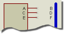
Repeat wiring
You would first click left at A, then B to place a horizontal wire between them. By clicking twice at C, you will invoke the Wire Repeat function which will then place a wire between C and D. Clicking left twice on E will join E and F and so forth.
Wire Repeat copies exactly the way the previous wire was routed. If the previous wire was automatically routed then the repeated wire will also be automatically routed. On the other hand, if the previous wire was manually routed then its exact route will be offset and used for the new wire.
Dragging Wires
Although wires follow the general scheme of tag then drag, there are various special techniques that you can apply to them. In particular:
- If you point at a corner and drag then the corner simply follows the pointer.
- If you point in the middle of a horizontal or vertical wire segment, the segment will be dragged vertically or horizontally respectively and the adjacent segments will be stretched to maintain connectivity.
- If you point in the middle of a diagonal segment, or at either end of the wire, then a corner will be created and then dragged. Note that in order for the latter to work, the object to which the wire connects must not be tagged, as otherwise Proteus will think you are trying to drag the object.
It is also possible to move a wire segment, or a group of wire segments using block move techniques.
To move a wire segment or group of segments:
- Drag out a tag-box around the wire segment(s) you wish to move. It is quite acceptable for this 'box' to be a line, lying along a single segment, if this is convenient.
- Move the mouse inside the tagbox (the cursor will change to indicate that objects can be moved).
- Depress the mouse and move in the direction orthogonal to the wire segments, as shown below.
- Release the mouse to finish.
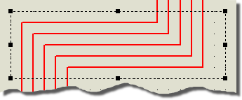
Moving a group of wires
A further technique provides a quick way of altering wiring topology, perhaps eliminating unwanted kinks in wires where they have been routed around an object which has since been moved.
To edit a wire's topology after routing:
- Tag the wire you wish to manipulate.
- Move the mouse over the segment that you want to adjust.
- Depress the left mouse button and move the mouse orthogonally as indicated by the mouse cursor.
- Release the left mouse button when complete.
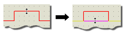
Removing kinks in a wire